
BWA by Eltex: Field tests


Introduction

The figures in a datasheet are one thing, but actual performance in the field is quite another. This is especially true when it comes to wireless broadband access, where distance, obstacles and weather can drastically change the outcome.
Manufacturers often specify only the channel speed according to a certain standard in the specifications for Wi-Fi equipment, rarely mentioning actual performance figures.
We believe it is important to share the test results with users of our devices so that they have an idea of the capabilities of Eltex equipment in reality, not just on paper. To this end, we have created a special test area in the Moscow region, where large-scale tests are conducted under various conditions.
In this article, you will learn about the results of research into the performance of Wi-Fi 6-based broadband wireless access equipment by Eltex: wireless bridges, base stations and user stations.
The test site
The test area in the Moscow region is located far enough from the capital to eliminate the influence of intense urban radio interference, but at the same time provides convenient logistics for the engineering team. The area’s terrain was chosen taking into account the conditions: elevation changes, mixed forests, open spaces and buildings of varying heights.
As opposed to locations in large cities, where it is impossible to predict the level of interference, controlled testing conditions were created, including the ability to understand the level of wireless interference and take its impact on the results into account.
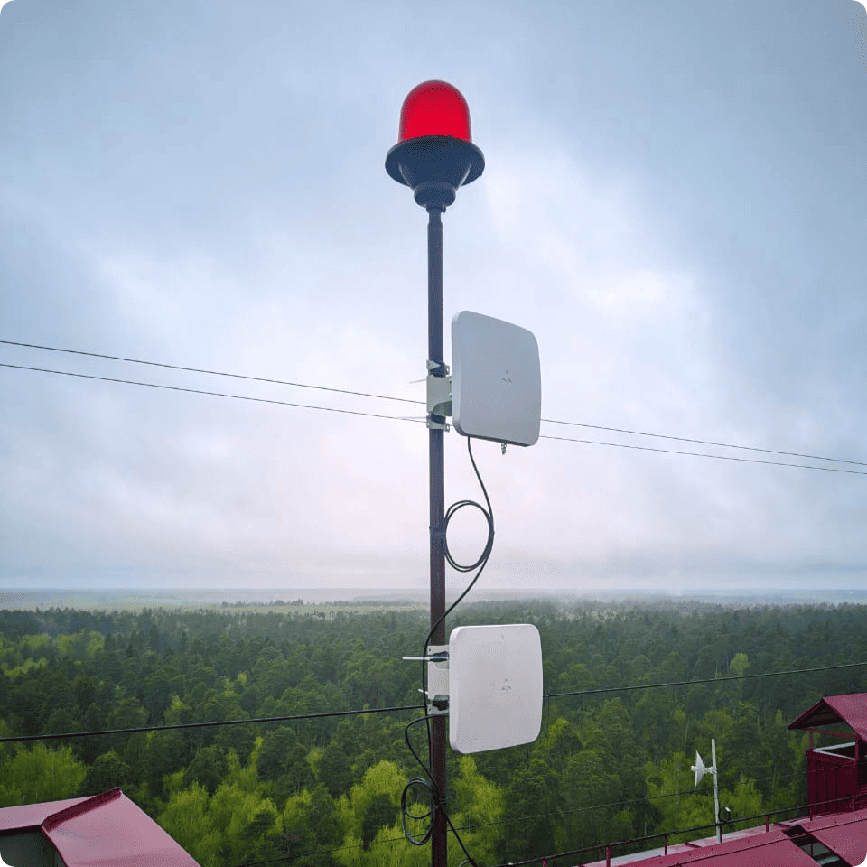
There were 10 measurement points at the test site. Taking into account the amount of equipment being tested and the connection type (PTP or PMP), radio links were built between different pairs of points at distances of 0.1–34 km from the headend. Depending on the tasks, the equipment under test is installed on masts of variable height or on the roofs of buildings of different heights. This makes it possible to simulate various scenarios, from connecting users to creating backbone channels.
Equipment tested
BWA devices by Eltex were tested. Equipment supporting the 2.4 and 5 GHz bands operates on the basis of the Wi-Fi 6 standard, while devices supporting 6 GHz operate on the basis of Wi-Fi 6E.
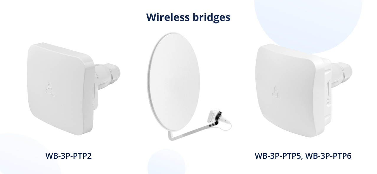
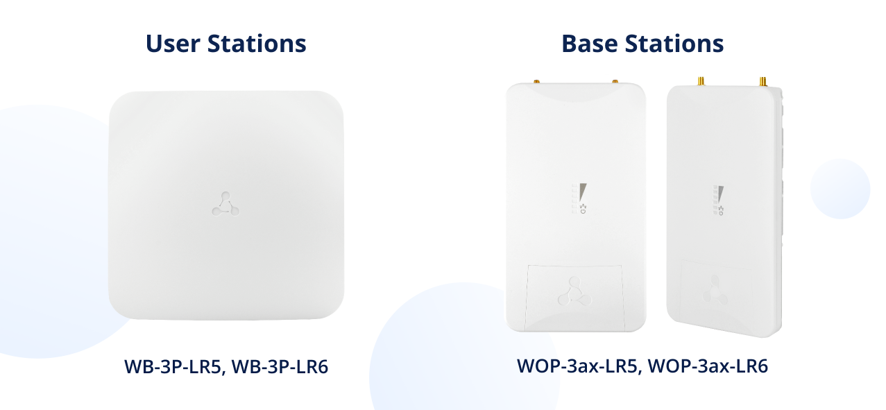
Wireless bridges: | User stations: | Base stations: | ||
WB-3P-PTP2 | WB-3P-LR5 | WOP-3ax-LR5 (5 GHz) | ||
WB-3P-PTP5 | WB-3P-LR6 | WOP-3ax-LR6 (6 GHz) | ||
WB-3P-PTP6 |
|
To view the technical specifications, click the name of the device.
- MCS was an active modulation scheme for each distance;
- bandwidth in laboratory conditions is the maximum speed measured for a given MCS under ideal conditions;
- real bandwidth is the actual measured transmission speed, taking into account environmental factors.
Important information
First, let's outline the conditions and parameters that should be considered when reviewing the test results.
Testing environment
Testing began in spring 2024 with the arrival of the first WB-3P-PTP2 samples and continues to this day to improve the performance of the devices. Measurements were taken in clear weather, without precipitation, at distances ranging from 0.1 to 34 kilometers in urban areas.
Traffic
Traffic generators were used at both ends of the radio link to obtain objective data on bandwidth without the influence of network line characteristics on the results. The generator on the transmitting side created test traffic that was transmitted using the devices under test, and on the receiving side, the similar generator received it, ensuring accurate measurement of the real bandwidth. This helped to create identical conditions for all test subjects.
Frequencies
BWA devices operating in the 5 and 6 GHz bands have a bandwidth of up to 160 MHz; those operating in the 2.4 GHz band have a bandwidth of up to 40 MHz. Testing was conducted for the 20 and 40 MHz frequency bands, which are the most popular in Russia. Transmission power was at its maximum in all cases. The least congested channels were selected in each band so that external interference would not affect the measurement results.
Connection schemes
A connection scheme specific to each type of equipment was selected. Wireless bridges were tested in a point-to-point (PTP) scheme, while base stations were tested together with user stations in a point-to-multipoint (PMP) scheme.
Technologies
A special feature of the tests was the inclusion of a proprietary implementation of TDD (Time Division Duplex) technology in the equipment, which helps to avoid collisions in the wireless network. It is available on Eltex BWA devices with support for Wi-Fi 6. For a detailed description of this technology read an article about the evolution of Eltex BWA solutions.
Here is the brief description. TDD works with fixed 10-millisecond frames divided into two equal slots for data transmission and reception. What TDD provides:
- In the PTP scheme used to connect bridges, guaranteed sequential transmission in both directions is ensured to eliminate collisions at long distances.
- In the PMP scheme used to connect base and user stations, the time for transmitting and receiving traffic is distributed among all transmitting and receiving devices. The features of bandwidth distribution will be described below.
Antennas
Two versions of the wireless bridges were tested:
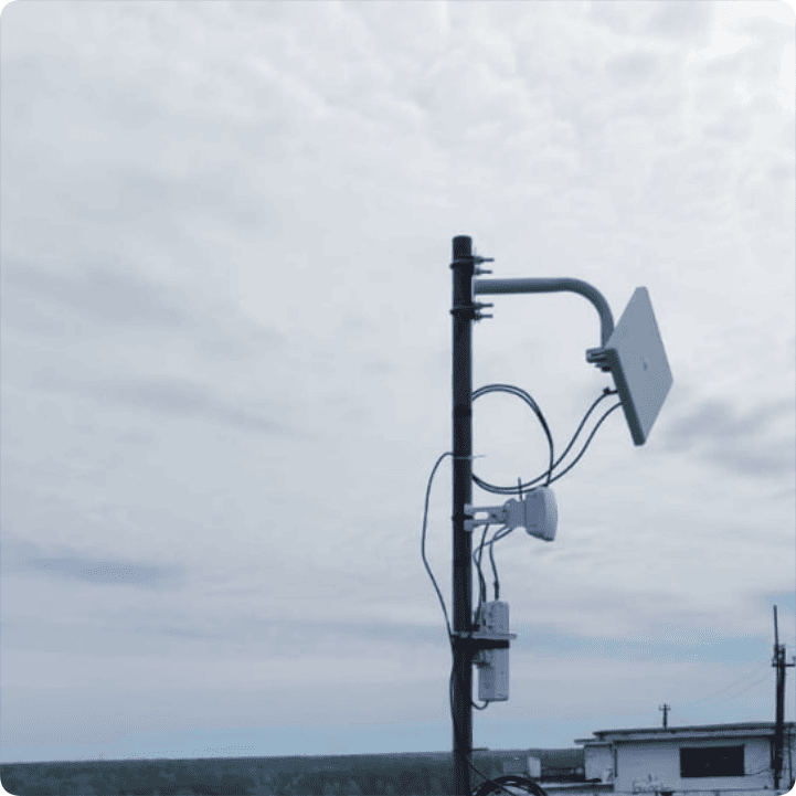
- One using built-in sector antennas with a 65° (H/V) beam width for 5 and 6 GHz models, and 60° (H/V) for the 2.4 GHz model. Gain is 9 dBi for 5 and 6 GHz models, 8 dBi for 2.4 GHz model.
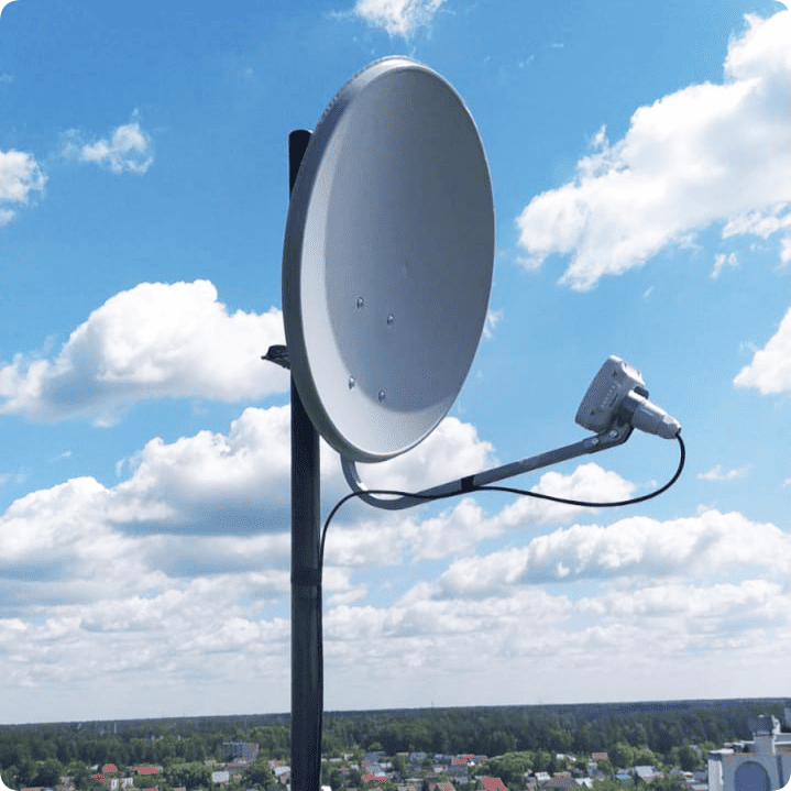
- Another one connected to an external parabolic offset antenna measuring 45×49.5 cm. Its main parameters are shown in the table below.

For base stations 5, a sector antenna for the 6 GHz band with a gain of 16 dBi was used. Directional diagram: horizontal 90°, vertical 8°.
Metrics
During testing, the modulation index and MCS (Modulation and Coding Scheme) values were recorded, which are dynamically selected by the equipment depending on the quality of the radio channel. The higher the MCS index (from MCS0 to MCS11 for Wi-Fi 6), the higher the transmission speed, but a high signal strength is required. As the distance between devices increases, the signal strength decreases, leading to an automatic switch to more stable but slower modulation schemes with higher noise immunity and lower spectral efficiency.
The following parameters were taken into account in the measurements:
- MCS was an active modulation scheme for each distance;
- bandwidth in laboratory conditions is the maximum speed measured for a given MCS under ideal conditions;
- real bandwidth is the actual measured transmission speed, taking into account environmental factors.
As you are now familiar with conditions and parameters, you can get to the testing and results.
Testing wireless bridges
WB-3P-PTP2 bridges (2.4 GHz)
The 2.4 GHz band is traditionally considered to have the most interference, but with the right approach and equipment, it is possible to use it for stable communication over moderate distances.
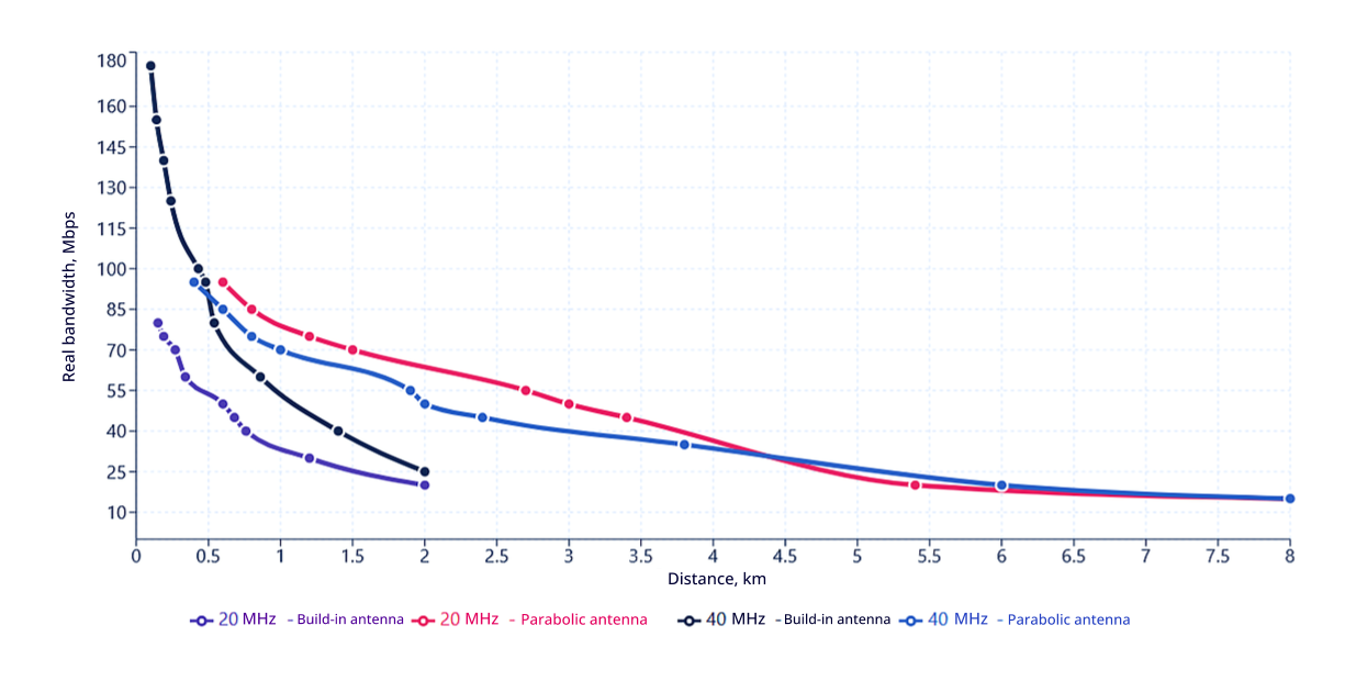
When operating in the 20 MHz band on a built-in sectoral antenna, the WB-3P-PTP2 shows a real bandwidth of up to 80 Mbps at a distance of 0.15 km (MCS11), gradually decreasing to 20 Mbps at a distance of 2 km (MCS3). At the same time, the maximum bandwidth in laboratory conditions is 190 Mbps for MCS11 and 45 Mbps for MCS3.
The use of a parabolic antenna radically changes the picture. At a distance of 0.6 km, the maximum real network bandwidth is 95 Mbps (MCS11), which is half the maximum of 190 Mbps for this modulation scheme. The operating range has increased to 8 km while maintaining a connection speed of 15 Mbps (MCS3) – three times lower than the 45 Mbps in laboratory for this modulation scheme. At a distance of 2.7 km, the device's bandwidth is 55 Mbps (MCS7) – almost three times more than the results with the built-in sector antenna at a distance of 2 km (20 Mbps on MCS3).
Switching to the 40 MHz band results in even greater bandwidth, but in the 2.4 GHz range, the use of a wide band increases the likelihood of interference from neighboring networks and other radio sources. The laboratory maximum of 460 Mbps (MCS11) translates to a real bandwidth of 175 Mbps (MCS11) over short distances of 0.1 km. Even with a built-in antenna, the device is capable of transmitting 40 Mbps at a distance of 1.4 km (MCS3) – more than twice lower than the 90 Mbps in laboratory. The real speed is high enough to connect buildings within an industrial site or urban area.
WB-3P-PTP5 wireless bridges: balance of speed and range
The 5 GHz wireless bridge demonstrated a correlation between bandwidth and communication range. Less spectrum congestion compared to 2.4 GHz gives it a noticeable advantage.
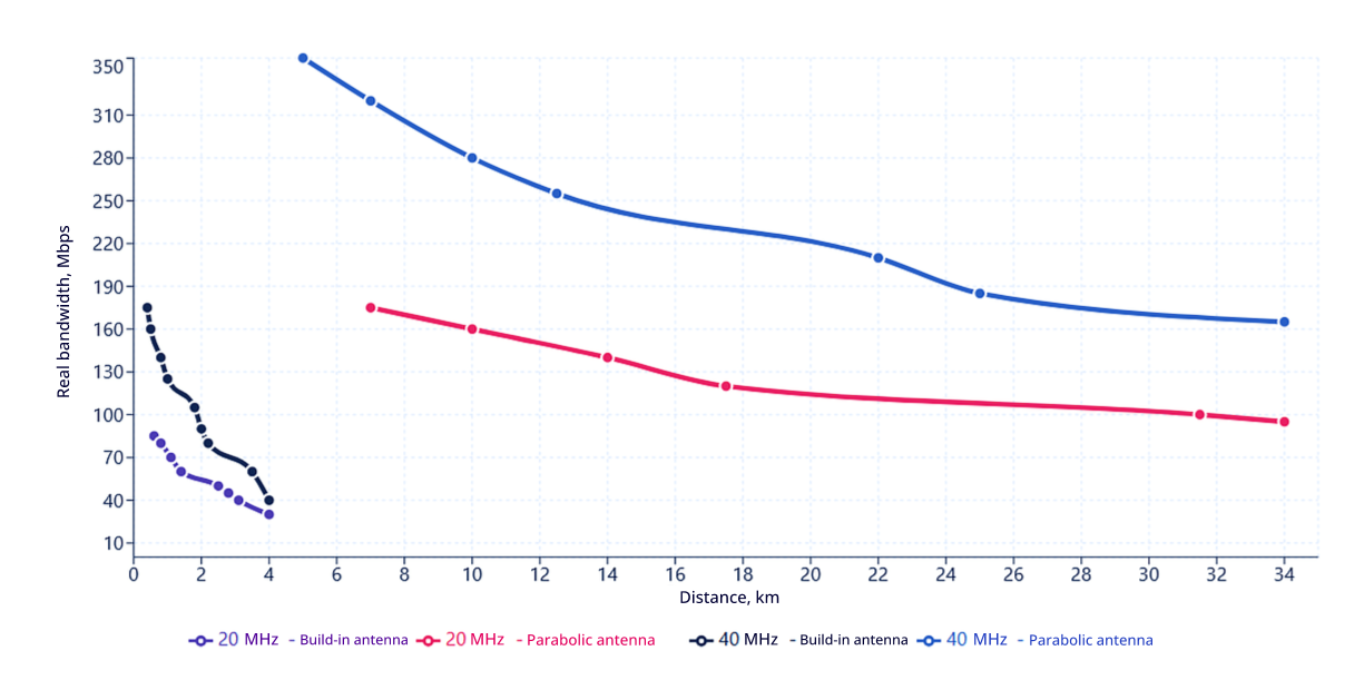
In the 20 MHz band, when using the built-in antenna, the device shows a real bandwidth of up to 85 Mbps at a distance of 0.6 km (MCS11), which is about 39% of the maximum of 220 Mbps for this modulation scheme. At a distance of 4 km, the bridge has a stable output of 30 Mbps (MCS4) – 40% of the 75 Mbps in laboratory for this modulation scheme.
Connecting a parabolic antenna makes it possible to create backbone channels over long distances. At a distance of 7 km, the device provides a speed of 175 Mbps (MCS11) – about 80% of the 220 Mbps laboratory maximum. The maximum test range of the test site is 34 km. At this distance, the bridges consistently transmitted data at a speed of 95 Mbps (MCS6) – about 79% of the 120 Mbps laboratory maximum, which is an excellent result for this class of equipment.
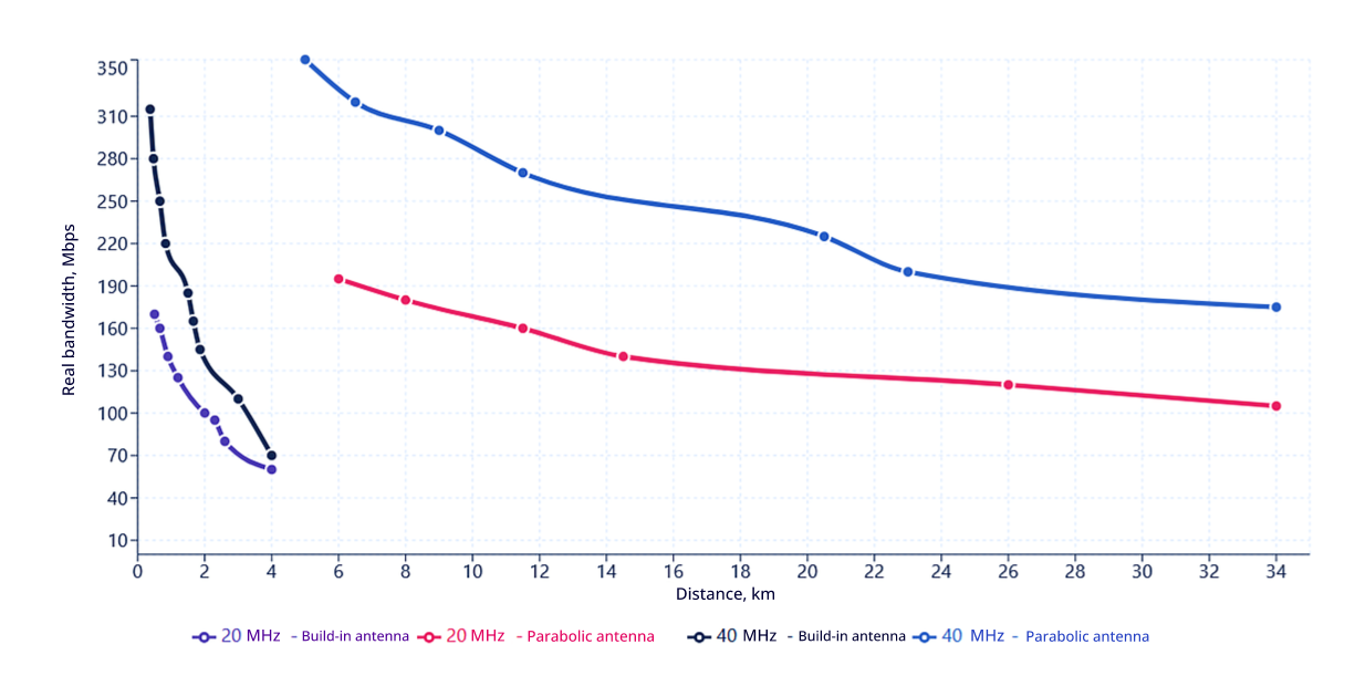
The 40 MHz band further unlocks the potential of the range. Using the built-in sector antenna, the bridge transmits data at speeds of up to 175 Mbps at a distance of 0.4 km (MCS11) – about 39% of the 445 Mbps laboratory maximum. At a distance of 4 km, the device outputs 40 Mbps (MCS3), which is 38% of 105 Mbps for this modulation scheme.
With a parabolic antenna, the device achieved a real speed of 350 Mbps at a distance of 5 km (MCS11) – about 79% of the laboratory maximum of 445 Mbps. At the maximum distance of the test site, 34 km, the bridge provides 165 Mbps for MCS5 – about 79% of the 210 Mbps measured in the laboratory for this modulation scheme.
A distinctive feature of operation in the 5 GHz band is the high predictability of performance. Unlike 2.4 GHz, where performance can vary significantly depending on interference and other factors, the 5 GHz band offers stable performance with deviations of ±5% from actual performance values.
WB-3P-PTP6 wireless bridges (6 GHz): clear air
The main advantage of using 6 GHz solutions is the minimal level of interference from other systems. This allows the theoretical potential of the equipment to be realized to a much greater extent than in the 2.4 and 5 GHz bands.
In the 20 MHz band, when using a built-in sector antenna, the maximum real speed was 170 Mbit/s at a distance of 0.5 km (MCS11) – about 77% of the maximum of 220 Mbit/s for this modulation scheme. This is significantly higher than the corresponding figure for the 2.4 and 5 GHz bands. At a distance of 4 km, the device provides 60 Mbps (MCS4) – 80% of the 75 Mbps laboratory maximum for this modulation scheme. The ratio of laboratory and real bandwidth is significantly different for 2.4 and 5 GHz devices compared to a 6 GHz bridge.
For example, in the 20 MHz band for a 2.4 GHz wireless bridge using an internal antenna at a distance of 0.6 km, the ratio of laboratory bandwidth to real bandwidth is approximately 43% (190 Mbps vs. 80 Mbps), for a 5 GHz wireless bridge, it is 38% (220 Mbps vs. 85 Mbps), and for a 6 GHz wireless bridge, it is 77% (220 Mbps vs. 170 Mbps).
At the same time, for all devices, the ratio flattens out as the distance increases.
This indicates a significant advantage of the 6 GHz band in terms of efficiency of radio frequency spectrum utilization. The flattening of the ratio with increasing distance for wireless bridges of all bands is a natural process: at long distances, the main limiting factor is signal attenuation, rather than interference from surrounding sources.
With a parabolic antenna in the 20 MHz band at a maximum test range of 34 km, the real bandwidth was 105 Mbps (MCS6) – more than 80% of the 120 Mbps laboratory result for this modulation scheme.
In the 40 MHz band, the results are even higher. When using the built-in sector antenna at a distance of 0.37 km, the real bandwidth was 315 Mbps (MCS11) – 70% of the 450 Mbps laboratory maximum. At a distance of 4 km, the bridge delivers 70 Mbps (MCS3) – 67% of the 105 Mbps laboratory result for this modulation scheme.
In tests with a parabolic antenna for a 40 MHz band at a distance of 5 km, the device provides 350 Mbps (MCS11) – about 78% of the 450 Mbps maximum. At the maximum test range of 34 km, the speed was 175 Mbps (MCS5) – 83% of the 210 Mbps laboratory result for this modulation scheme.
6 GHz wireless bridges showed minimal decrease in performance with increasing distance. While at 2.4 GHz the actual speed is only 42% of the laboratory speed at short distances, at 6 GHz this figure reaches 77%, which indicates high channel efficiency.
Testing base and user stations
The base and user stations were tested using their characteristic point-to-multipoint configuration with the sectoral antenna mentioned above. The total network capacity is determined by the connection of the furthest user station. After that, the guaranteed speed per user station can be calculated using the following formula
С1= Сwlan / n[1...64],
where Сwlan is the total network capacity in real conditions, Mbps;
n[1...64] is the number of connected user stations, from 1 to 64.
WOP-3ax-LR5 base station, WB-3P-LR5 (5 GHz) user station
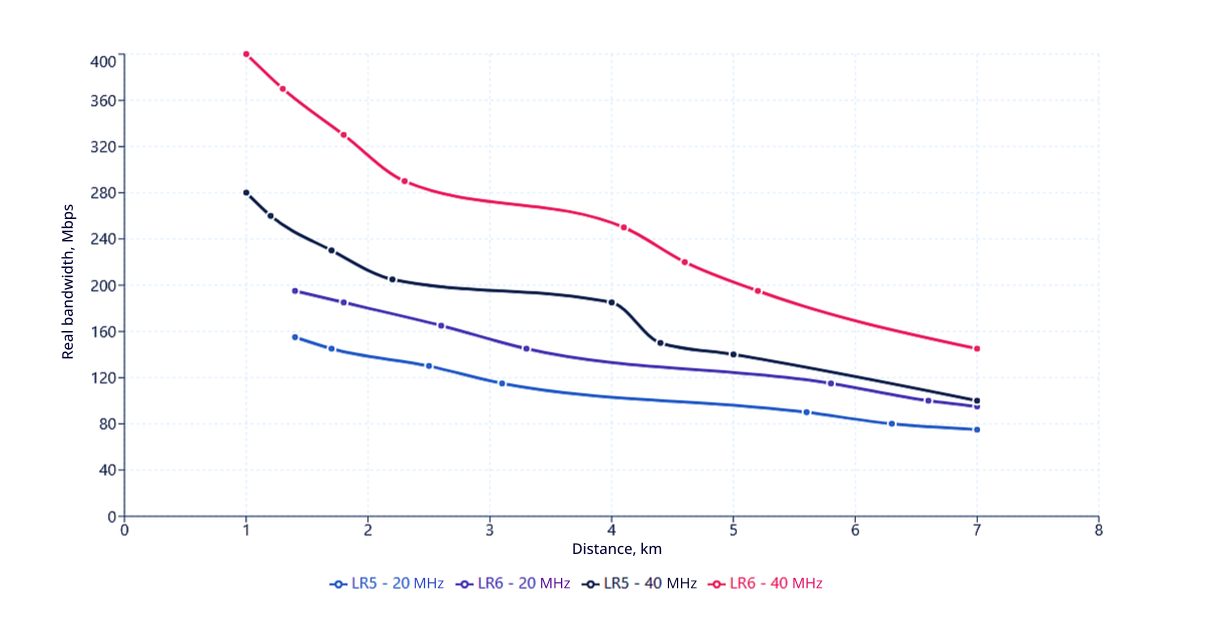
The WOP-3ax-LR5 base station paired with WB-3P-LR5 user stations was tested at distances of up to 7 km. In the 20 MHz band, the real network capacity is 155 Mbps (MCS11) at a distance of 1.4 km, gradually decreasing to 75 Mbps (MCS5) at the maximum distance.
In 40 MHz mode, the results are even better: 280 Mbps (MCS11) at a distance of 1 km and 100 Mbps (MCS5) at 7 km.
When the base station is fully loaded (with 64 users connected), each user is guaranteed to receive 1.2–4.4 Mbps, depending on the distance. Keep in mind that these figures are achieved using TDD, mentioned above.
WOP-3ax-LR6 + WB-3P-LR6 (6 GHz)
The 6 GHz equipment showed the best results in terms of network capacity. In the 20 MHz band, the real capacity reaches 195 Mbps (MCS11) at a distance of 1.4 km and remains at 95 Mbps (MCS5) at a distance of 7 km – 27% higher than 5 GHz devices.
In 40 MHz mode, the advantages become more apparent: 400 Mbps (MCS11) at a distance of 1 km and 145 Mbps (MCS4) at 7 km. At full load, each of the 64 clients will receive between 2.3 and 6.25 Mbps of guaranteed bandwidth, depending on the distance.
Comparison with the previous generation
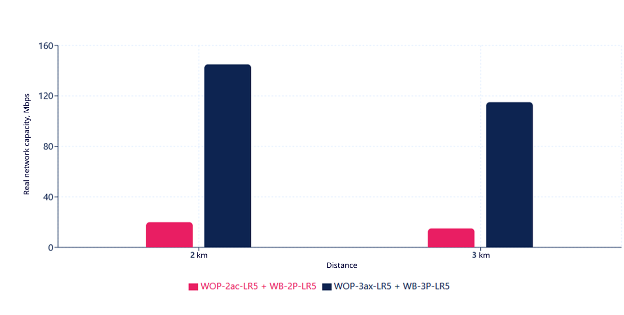
The performance of the WOP-3ax-LR5 base station paired with the WB-3P-LR5 user station was compared with Wi-Fi 5 devices – WOP-2ac-LR5 and WB-2P-LR5. We found out the difference between devices operating on different Wi-Fi standards in the 5 GHz band and used two distances for analysis – 2 and 3 km, with a bandwidth of 20 MHz.
At a distance of 2 km, the new generation of Wi-Fi 6 devices shows a maximum real capacity of 145 Mbps (MCS10) compared to 20 Mbps (MCS3) for their Wi-Fi 5 predecessors.
At a distance of 3 km, the network capacity of the new generation of Wi-Fi 6 devices is 115 Mbps (MCS8) compared to 15 Mbps (MCS2) for previous generation devices.
A sevenfold increase in performance at both distances demonstrates the qualitative difference between generations of BWA devices by Eltex operating in the same 5 GHz band.
Conclusion
Manufacturers rarely publish the actual performance figures for their devices. Usually, most limit themselves to theoretical maximums from the specifications. At the same time, there is a difference between the declared and actual characteristics of any Wi-Fi equipment in real operating conditions.
We publish not only figures from lab tests, but also the real performance indicators of broadband wireless access equipment by Eltex so that customers understand what to expect and what speeds there are in real operation.
Eltex devices for wireless broadband access solve a wide range of tasks, from creating backbone channels to connecting remote users “over the air.” And our tests have shown that they do so with high performance.
We continue to develop our products. A major update for BWA devices will be released this fall, including the following improvements:
- reduction of frame time to 5 ms in TDD;
- adjustment of the DL/UL slot ratio for TDD;
- automatic detection of the distance between the access point and the client;
- support for management and monitoring of WB-3P-PTP2/5/6 wireless bridges in the system.
In the future:
- automatic DL/UL slot ratio selection mode depending on traffic volume;
- inter-sector synchronization on WOP-3ax-LR5/6 base stations for the 5 and 6 GHz bands;
- support for ECCM management of base and user stations in the new product line.
Mentioned products
- Wi-Fi 5:
- 802.11ac
- MIMO:
- 2x2
- Frequency range:
- 5150-5835 MHz
- Transmitter power:
- up to 28 dBm
- Wi-Fi 5:
- 802.11ac
- MIMO:
- 2x2
- Frequency range:
- 5150–6160 MHz
- Transmitter power:
- up to 28 dBm

- Wi-Fi 6:
- 802.11ax
- MU-MIMO:
- 2x2
- Frequency range:
- 5935–7125 MHz
- Power of the transmitter:
- up to 26 dBm
- Wi-Fi 6:
- 802.11ax
- MU-MIMO:
- 2x2
- Frequency range:
- 5150–5975 MHz
- Power of the transmitter:
- up to 27 dBm

- Wi-Fi 6:
- 802.11ax
- MU-MIMO:
- 2x2
- Frequency range:
- 5935–7125 MHz
- Power supply:
- PoE+ 48 V/56 V
- Wi-Fi 5:
- 802.11a/n/ac/ax
- MU-MIMO:
- 2x2
- Frequency range:
- 5150–5975 MHz
- Power supply:
- PoE+ 48 V/56 V
- Wi-Fi 6:
- 802.11ax
- MU-MIMO:
- 2x2
- Frequency range:
- 5935–6425 MHz
- Power of the transmitter:
- up to 26 dBm

- Wi-Fi 6:
- 802.11ax
- MU-MIMO:
- 2x2
- Frequency range:
- 5150–5975 MHz
- Power of the transmitter:
- up to 27 dBm

- Wi-Fi 6:
- 802.11ax
- MU-MIMO:
- 2×2
- Frequency range:
- 2400–2483.5 MHz
- Transmitter power:
- 26 dBm